STK Premium (Air) or STK Enterprise
You can obtain the necessary licenses for this tutorial by contacting AGI Support at support@agi.com or 1-800-924-7244.
This lesson requires an internet connection and version 12.9 of the STK software or newer to complete in its entirety.
The results of the tutorial may vary depending on the user settings and data enabled (online operations, terrain server, dynamic Earth data, etc.). It is acceptable to have different results.
Capabilities and tools covered
This lesson covers the following capabilities and tools of the Ansys Systems Tool Kit® (STK®) digital mission engineering software:
- STK Pro
- Aviator
- Aviator Performance Model Wizard
- Export Ephemeris/Attitude tool
Problem statement
Aircrew mission planners require analytical tools that allow them to quickly create an aircraft mission profile that can be used anywhere around the world without recreating the flight profile over and over again. They need tools that can quickly create a model of a specific aircraft type using a subset of performance models as well as a standard flight profile, which users who are familiar with the STK application’s Aviator capability can use and reuse.
Solution
Use the STK application's core capabilities and the Aviator Performance Model Wizard to create an aircraft model that can be used in multiple scenarios where the aircraft type and specifications are unchanged. Create a flight profile using the custom model for an Aircraft object, then export the aircraft's mission profile as an external ephemeris file. Import the external ephemeris file into a different Aircraft object and make minor changes, placing the new aircraft in a selected location while employing the same mission profile. Finally, load the aircraft model you created earlier into another Aircraft object through the Aviator Catalog Interface to plan a new mission for the same type of aircraft.
What you will learn
Upon completion of this tutorial, you will understand the following:
- How to use the Aviator Performance Model Wizard to create an aircraft model
- How to create an external ephemeris file of an Aviator-built Aircraft mission
- How to import an external ephemeris file into an Aviator-built Aircraft mission
- How to use an aircraft model with other Aircraft objects and in other scenarios
Video guidance
Watch the following video. Then follow the steps below, which incorporate the systems and missions you work on (sample inputs provided).
Creating a new scenario
First, you must create a new scenario and then build from there.
- Launch the STK application (
 ).
). - Click
 Create a Scenario in the Welcome to STK dialog box.
 - Enter the following in the STK: New Scenario Wizard:
- Click when you finish.
- Click Save (
 ) when the scenario loads. The STK application creates a folder with the same name as your scenario for you.
 - Verify the scenario name and location in the Save As dialog box.
- Click .
| Option | Value |
|---|---|
| Name | Aviator_Tools |
| Location | Default |
| Start | Default (recommend changing the time to 18:00:00.000 UTCG for daylight) |
| Stop | + 4 hr |
Save (![]() ) often during this scenario!
) often during this scenario!
Using the Aviator Catalog Manager
Aviator provides a catalog structure for the loading and saving of aircraft, airports, NAVAIDs, runways, VTOL points, and waypoints. Each of these mission elements has an associated catalog in the STK application. The Aviator Catalog Manager is a utility that allows you to view the contents of catalogs, create new items, copy or edit existing items, and search for specific items.
Opening the Aviator Catalog Manager
Open the Aviator Catalog Manager from the Utilities menu.
- Select the Utilities menu.
- Select Aviator Catalog Manager... (
 ).
).
Loading navigation data using the Aviator Catalog Manager
Load an ARINC424 data file containing navigation information. ARINC424 data files are the only valid data sources for NAVAID and airport sites.
- Resize the Aviator Catalog Manager window by extending it out to the right so that you can see more space in the large blank area.
- Expand (
 ) Runway (
 ).
). - Select ARINC424 runways (
 ).
). - Click the Use Master Data File ellipsis (
 ).
). - Navigate to <Install Dir>\Data\Resources\stktraining\samples when the Open dialog box appears.
- Select the FAANFD18 data file.
- Click to select the file and to close the Open dialog box.
- Click when you return to the Aviator Catalog Manager.
- Close (
 ) the Aviator Catalog Manager.
Inserting an Aircraft object
Insert an Aircraft object, for which you will create a flight profile.
- Bring the Insert STK Objects tool (
 ) to the front.
 - Select Aircraft (
 ) in the Select An Object To Be Inserted list.
 - Select Insert Default () in the Select A Method list.
- Click .
- Right-click on Aircraft1 () in the Object Browser.
- Select Rename in the shortcut menu.
- Rename Aircraft1 () Tanker1.
Using the Aviator capability
The Aviator capability provides an enhanced method for modeling aircraft. It is more accurate and more flexible than the standard Great Arc propagator. With Aviator, the aircraft's route is modeled by a sequence of curves parametrized by well-known performance characteristics of aircraft, including cruise airspeed, climb rate, roll rate, and bank angle. The precise state of an aircraft at any given time can be computed analytically—swiftly, and without excessive data storage needs.
Selecting Aviator as the propagator
To utilize the Aviator capability, you must first set your aircraft to use Aviator as its propagator.
- Right-click on Tanker1 () in the Object Browser.
- Select Properties (
 ) in the shortcut menu.
 - Select the Basic - Route page when the Properties Browser opens.
- Open the Propagator drop-down list.
- Select Aviator.
- Click to accept the change and to keep the Properties Browser open.
- Read the information in the Flight Path Warning dialog box.
- Click to set the scenario globe reference to Mean Sea Level (MSL) and the Animation mode to X Real Time.
- Click to close the Fight Path Warning dialog box.
Aviator performs best in the 3D Graphics window when the surface reference of the globe is set to MSL instead of the default reference of WGS84. Likewise, setting the animation mode to X Real Time allows for smoother animation and better data display performance.
Using the Performance Model Wizard
In Aviator, an
The
You will use basic performance models for your aircraft. Basic models are used to quickly design an aircraft. You will modify them with some basic performance characteristics of a real-world tanker aircraft model. While you could enter propulsion, aerodynamics, and other performance data to more accurately model your tanker aircraft using the Performance Model Wizard, you will forgo adding many of these finer details in this exercise to better focus on the tutorial's learning goals.
Creating a new performance model
Open the Performance Model Wizard to create a new aircraft model and its associated performance models.
- Click Performance Model Wizard (
 ) in the Initial Aircraft Setup toolbar.
 - Enter Tanker in the Aircraft Model Name field in the Performance Model Wizard.
- Enter Tanker in the Performance Model Name field.
- Click .
Setting the Acceleration performance model
The
- Select Acceleration (
 ) in the Performance Models list of the Tanker dialog box.
 - Select Simple in the Select an acceleration strategy list.
- Click two times.
Setting the fixed-wing reference surface area
You know from publicly available data that your tanker aircraft has an approximate wing surface area of 226 square meters. You can include this parameter in your Acceleration performance model.
- Enter 226 m^2 in the Reference Surface Area field.
- Click two times.
Setting the Climb performance model
The
- Ensure Climb () is selected in the Performance Models list.
- Select AGI Basic Climb Model in the Select a climb performance model list.
- Click .
- Enter 4900 ft/min in the Altitude Rate field.
- Click .
Setting the Cruise performance model
The
- Ensure Cruise () is selected in the Performance Models list.
- Select AGI Basic Cruise Model in the Select a cruise performance model list.
- Click .
- Enter 24000 ft in the Default Cruise Altitude field.
- Click .
Setting the Descent performance model
The
- Ensure Descent () is selected in the Performance Models list.
- Select AGI Basic Descent Model in the Select a descent performance model list.
- Click two times.
Setting the Landing performance model
The
- Ensure Landing () is selected in the Performance Models list.
- Select AGI Basic Landing Model in the Select a landing performance model list.
- Click .
- Enter 7.5 kft in the Sea Level Ground Roll field.
- Click .
This is equivalent to 7,500 feet.
Setting the Takeoff performance model
The
- Ensure Takeoff () is selected in the Performance Models list.
- Select AGI Basic Takeoff Model in the Select a takeoff performance model list.
- Click .
- Enter 178 nm/hr in the Takeoff Speed field.
- Enter 9 kft in the Sea Level Ground Roll field.
- Click .
- Click to accept your changes and to keep the Properties Browser open.
Building Tanker1's flight route
Now that you have designed your tanker aircraft model, you can begin designing its flight profile. Tanker1 will fly its mission in the vicinity of the Pittsburgh International Airport.
Adding an STK Static Object Waypoint site
An
- Click Insert Procedure After (
 ) in the Procedures and Sites toolbar.
 - Select Waypoint from Catalog (
 ) in the Select Site Type list in the Site Properties dialog box.
 - Enter Pittsburgh in the Filter field.
- Select the Enter key.
- Select PITTSBURGH INTL (
 ) in the inside ARINC424 airports (
 ).
). - Click .
Note that PITTSBURGH INTL(![]() ) is read only (
) is read only (![]() ) and cannot be modified.
) and cannot be modified.
Selecting a Basic Point to Point procedure
A
- Select Basic Point to Point (
 ) in the Select Procedure Type list of the Procedure Properties dialog box.
 - Note that the Use Aircraft Default Cruise Altitude option is selected by default, and that the Altitude is set to 24000 ft MSL. This matches the value you set for your Cruise performance model.
- Click .
- Click to accept your changes and to keep the Properties Browser open.
Selecting an End of Previous Procedure site
An
- Click Insert Procedure After () in the Procedures and Sites toolbar.
- Select End of Previous Procedure (
 ) in the Select Site Type list of the Site Properties dialog box.
 - Click .
Selecting a Basic Maneuver procedure
A
- Select Basic Maneuver (
 ) in the Select Procedure Type list in the Procedure Properties dialog box.
 - Select the Horizontal / Navigation tab.
- Note that the Strategy is set to Straight Ahead.
- Set the following in the Basic Stop Conditions panel:
- Click three times.
- Click to accept your changes and to keep the Properties Browser open.
| Option | Value |
|---|---|
| Time of Flight | Cleared |
| Downrange | 25 nm |
This procedure will end if your aircraft reaches zero pounds of fuel or flies straight ahead for 25 nautical miles, whichever comes first.
Selecting another End of Previous Procedure site
The end of the previous procedure is used as the waypoint for the next procedure in the flight route.
- Click Insert Procedure After () in the Procedures and Sites toolbar.
- Select End of Previous Procedure () in the Select Site Type list of the Site Properties dialog box.
- Click .
Inserting a Holding – Racetrack procedure
A racetrack holding procedure is a patrol in a rectangular oval. The holding point for the procedure is the point at which the aircraft enters and exits the holding circle and is the reference point for procedures that are set to end on a course to the next procedure. This holding point is defined by a bearing and range from the procedure site; the racetrack is oriented parallel to the line of bearing. The site of a holding procedure is only a reference point for the holding pattern, and may not be encompassed by the aircraft's flight path.
- Select Holding - Racetrack (
 ) in the Select Procedure Type list in the Procedure Properties dialog box.
 - Enter the following in the Hold Options panel:
- Enter 2.00 in the Turn Factor field in the Enroute Options panel.
- Click .
- Click to accept your changes and to close the Properties Browser.
| Option | Value |
|---|---|
| Bearing | 90 deg |
| Range | 40 nm |
| Width | 15 nm |
| Length | 50 nm |
| Entry Maneuver | Use Alternate Entry Points |
| Turn direction | Inbound Right Turn |
| Number of Full Turns | 5 |
Viewing Tanker1's flight route in the 2D Graphics window
Use the 2D Graphics window to get a good view of the flight route.
- Bring the 2D Graphics window to the front.
- Zoom in until you can see the flight route
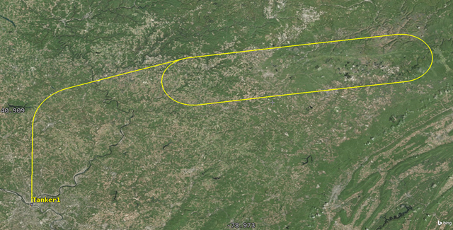
2D View of TANKER1's FLIGHT ROUTE
Exporting ephemeris and attitude data
You can create vehicle attitude or ephemeris data for all types of vehicles by using the
Once you have the ephemeris data, organized in a properly formatted table, in any ephemeris file, you can then import it into the STK application and use it anywhere else in the world, making minor changes to the location, altitude, etc. This can be used for any Aircraft object propagated with Aviator. It keeps you from having to rebuild the Aircraft object’s properties each time you want to use the same aircraft in another mission.
- Right-click on Tanker1 () in the Object Browser.
- Select Ephemeris/Attitude... in the shortcut menu.
- Review the default values in the Create Data File dialog box.
- Click .
- Save the file in your scenario folder.
- Click to close the Create Data File dialog box.
Using ephemeris and attitude data with another aircraft
Now that you have created a flight profile for your tanker aircraft and exported it as an external ephemeris file, you can import its ephemeris data to use with another Aircraft object in a new, selected location, employing the same flight profile.
Inserting a second Aircraft object
Insert an Aircraft object that will use the external ephemeris file you created.
- Insert an Aircraft () object using the Insert Default () method.
- Rename Aircraft2 () Tanker2.
Changing the propagator to Aviator
To use the external ephemeris file, you must select Aviator as the aircraft's propagator.
- Open Tanker2’s () Properties ().
- Select the Basic – Route page when the Property Browser opens.
- Open the Propagator drop-down list.
- Select Aviator.
- Click to accept your change and to keep the Properties Browser open.
Inserting a Reference State procedure
To load an external ephemeris file into Aviator, add a Reference State procedure at the beginning of the mission to define existing flight conditions. A
- Click Insert Procedure After () in the Procedures and Sites toolbar.
- Select Reference State (
 ) in the Select Site Type list of the Site Properties dialog box.
 - Click .
Importing the external ephemeris file
The
- Select ExtEphem (
 ) in the Select Procedure Type list of the Procedure Properties dialog box.
 - Click the ellipsis () in the External Ephemeris File panel.
- Go to your scenario folder.
- Select Tanker1.e.
- Click .
Setting up Tanker2’s flight mode
Choose a flight type that describes the current attitude of the aircraft across the designated time period. In this instance, your flight route is level flight.
- Open the Flight Mode drop-down list in the Flight Config panel.
- Select Forward Flight – Cruise.
Moving Tanker2 to a different location
Tanker2 will fly its mission in the vicinity of Travis AFB.
- Select the Use Shift/Rotate check box in the Shift/Rotate panel.
- Click .
- Select ARINC424 airports (
 ) in the Waypoint Lat/Lon dialog box.
 - Enter Travis in the Filter field.
- Select the Enter key.
- Select TRAVIS AFB ().
- Click to close the Waypoint Lat/Lon dialog box.
- Click to close the Procedure Properties dialog box.
- Click to accept your changes and to close the Properties Browser.
The Shift/Rotate option allows you to move a given external ephemeris file to any point on the earth.
Viewing Tanker2's flight route in the 3D Graphics window
Tanker2 is above and centered over Travis AFB.
- Bring the 3D Graphics window to the front.
- Right-click on Tanker2 () in the Object Browser.
- Select Zoom To in the shortcut menu.
- Use your mouse to view Tanker2 () over Travis AFB and its flight route.
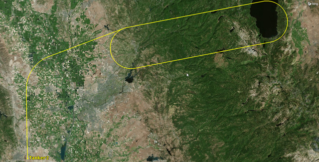
3D VIEW OF Tanker2's flight route
You can see that Tanker2 is utilizing the same flight profile as Tanker1.
Using an aircraft model with another Aircraft object
When creating the Tanker aircraft model, you created custom performance models to define its takeoff, climb, cruise, descent, and landing characteristics. You saved your custom aircraft model to the aircraft catalog in Aviator. Both aircraft models and individual performance models are stored in Aviator catalogs; they can be accessed through the
You can use your saved aircraft model when creating a flight profile that doesn’t use an external ephemeris file. Use the Tanker aircraft model you created earlier to fly a tanker from Altus Air Force Base (AFB) to Fairchild AFB via two VORTAC NAVAID sites.
Inserting a third Aircraft object
Insert an Aircraft object which will use the external ephemeris file.
- Insert an Aircraft () object using the Insert Default () method.
- Rename Aircraft3 () Tanker3.
Changing the propagator to Aviator
Select Aviator as the aircraft's propagator.
- Open Tanker3’s () Properties ().
- Select the Basic – Route page when the Property Browser opens.
- Open the Propagator drop-down list.
- Select Aviator.
- Click to accept your change and to keep the Properties Browser open.
Selecting an aircraft model
Apply the Tanker aircraft model to Tanker 3 by loading it from the Aviator Catalog Interface.
- Click Select Aircraft () In the Initial Aircraft Setup toolbar.
- Select Tanker (
 ) in the Select Aircraft dialog box.
 - Click to close the Select Aircraft dialog box.
- Click to accept your changes and to keep the Properties Browser open.
Note that the Tanker (![]() ) aircraft model is bounded by a purple box (
) aircraft model is bounded by a purple box (![]() ), meaning that it is in use in the current scenario. It is being used by the Tanker1 aircraft.
), meaning that it is in use in the current scenario. It is being used by the Tanker1 aircraft.
Selecting the takeoff runway site at Altus AFB
Since you have ARINC424 airport data available in the Aviator Catalog Manager, you can define a site using an airport in that data with a
- Click Insert Procedure After () in the Procedures and Sites toolbar.
- Select Runway from Catalog (
 ) in the Select Site Type list of the Site Properties dialog box.
 - Enter Altus in the Filter field.
- Select the Enter key.
- Select Altus AFB 17R 35L (
 ) under ARINC424 runways ().
 - Click .
Using the runway data available in the Aviator Catalog Manager, you know that runway 17R 35L is long enough for your tanker's 9,000-foot takeoff roll.
Selecting the Takeoff procedure
A
- Select Takeoff (
 ) in the Select Procedure Type list of the Procedure Properties dialog box.
 - Set the following options:
- Click .
- Click to apply the changes and to keep the Properties Browser open.
| Option | Value |
|---|---|
| Name | Altus AFB |
| Runway Heading The direction that the aircraft is pointing. - Use headwind runway | Selected |
| Runway Altitude Offset | 15 ft |
| Use Terrain for Runway Altitude | Selected |
Selecting the Alamosa NAVAID site
If you have ARINC424 NAVAID data available in the Aviator Catalog Manager, you can define a site using a NAVAID from that data with a
- Click Insert Procedure After () in the Procedures and Sites toolbar.
- Select Navaid from Catalog (
 ) in the Select Site Type list in the Site Properties dialog box.
 - Enter ALS in the Filter field.
- Select the Enter key.
- Select ALS (
 ) in the ARINC424 navaids(
 ) list.
 - Click .
ALS is the Federal Aviation Administration (FAA) designator for the Alamosa VORTAC in Colorado.
Selecting the Basic Point to Point procedure
Use a Basic Point to Point procedure to traverse the route to the Alamosa VORTAC.
- Select Basic Point to Point () in the Select Procedure Type list of the Procedure Properties dialog box.
- Click .
- Click to apply the changes and to keep the Properties Browser open.
Selecting the Twin Falls NAVAID site
Add the next NAVAID in the flight route.
- Click Insert Procedure After () in the Procedures and Sites toolbar.
- Select Navaid from Catalog () in the Select Site Type list in the Site Properties dialog box.
- Enter TWF in the Filter field.
- Select the Enter key.
- Select TWF () in the ARINC424 navaids() list.
- Click .
TWF is the FAA designator for the Twin Falls VORTAC in Idaho.
Selecting the Basic Point to Point procedure
Use a Basic Point to Point procedure to traverse the route between the two waypoints.
- Select Basic Point to Point () in the Select Procedure Type list of the Procedure Properties dialog box.
- Click .
- Click to apply the changes and to keep the Properties Browser open.
Selecting the landing runway site at Fairchild AFB
Tanker3 is landing at Fairchild AFB.
- Select Insert Procedure After () in the Procedures and Sites toolbar.
- Select Runway from Catalog () in the Site Properties / Select Site Type section.
- Enter Fairchild in the Filter field.
- Select the Enter key.
- Select FAIRCHILD AFB 05 23 () under ARINC424 runways ().
- Click .
Inserting a Landing procedure
A
- Select Landing (
 ) in the Select Procedure Type list in the Procedure Properties dialog box.
 - Set the following options:
- Click .
| Option | Value |
|---|---|
| Name | Fairchild AFB |
| Approach Mode | Intercept Glideslope |
| Runway Heading - Use headwind runway | Selected |
| Landing Options - Runway Altitude Offset | 15 ft |
| Landing Options - Use Terrain for Runway Altitude | Selected |
Viewing Tanker3's mission profile
The mission profile can display a variety of data describing the mission. The default profile displays the aircraft's altitude relative to its downrange distance.
- Look at the mission profile in the Mission Window.
- Click to accept your changes and to close the Properties Browser.
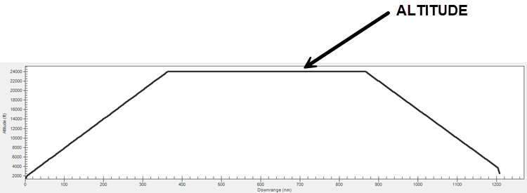
Tanker3 Mission Profile
Recall that you set the Tanker Cruise performance model to 24,000 feet. You can see that between the two VORTAC sites, Tanker3 maintains a cruising altitude of 24,000 feet.
Saving your work
Clean up your workspace and close out your scenario.
- Close any open windows except for the 2D and 3D Graphics windows.
- Save () your work.
- Close the scenario when finished.
Summary
This scenario was designed to show you how to configure an Aircraft object using Aviator and some of its tools. You used the Aviator Performance Model Wizard to create a custom aircraft model. You then designed a generic flight orbit for an Aircraft object. This mission profile might be used every day in one location, or it could be used somewhere else around the world. Next, you exported the Aircraft object's mission profile as an external ephemeris file. Then, you imported the external ephemeris file into a different Aircraft object, making minor changes, which placed the new aircraft in the selected orbit in a different location. Finally, you reused your custom aircraft model for an aircraft that flew a long-distance flight between two airfields. If you fly the same type of aircraft from multiple locations, you can use your aircraft models and mission profiles over and over. You don’t have to recreate your aircraft each time.