Part 1:
STK Pro, STK Premium (Air), STK Premium (Space), or STK Enterprise
You can obtain the necessary licenses for this tutorial by contacting AGI Support at support@agi.com or 1-800-924-7244.
The results of the tutorial may vary depending on the user settings and data enabled (online operations, terrain server, dynamic Earth data, etc.). It is acceptable to have different results.
Capabilities covered
This lesson covers the following capabilities of the Ansys Systems Tool Kit® (STK®) digital mission engineering software:
- STK Pro
Problem statement
Engineers and operators need an environment to quickly model and simulate their missions both analytically and visually.
Solution
The Ansys Systems Tool Kit® (STK®) digital mission engineering software provides a physics-based simulation environment for digital mission engineering. Your system and component models can interact in the STK application, enabling you to measure their performance in the context of the complete mission.
You can access the NASA Systems Engineering Handbook
What you will learn
To begin using the STK software, you need a basic understanding of the STK application's workflow and layout. In this tutorial, you will learn how to:
- Create a new scenario
- Save a scenario
- Understand the STK application windows
- Understand common tools
- Open and close a scenario
Video guidance
Watch the following video. Then follow the steps below, which incorporate the systems and missions you work on (sample inputs provided).
Creating a new STK scenario
In this section, you will learn to choose a central body for your scenario, create a new scenario, and then save your scenario.
Changing a central body
A central body in the STK application models the gravitational, atmospheric, ephemeris, and other properties of a celestial body. The catalog of central bodies in the STK application includes the known planets, the Sun, the Moon, and other bodies of common interest. If enabled, the Central Body drop-down menu appears in the STK: New Scenario Wizard. Select from the list of planets to designate the scenario's primary central body. Earth is the STK application's default primary central body; to enable additional central body Planetary Options, you can do so using the View menu.
- Launch the STK (
 ) application.
 - Select the View menu when the STK application opens.
- Select Planetary Options in the View menu so that a check mark appears next to it.
This will enable you to choose a central body in the STK: New Scenario Wizard.
Creating a new scenario
Create a new STK ![]() ) object defines the context in which the properties and behavior of other objects are defined.
) object defines the context in which the properties and behavior of other objects are defined.
For additional information about this tool, visit the New Scenario Wizard help page.
- Click
 Create a Scenario in the Welcome to STK dialog box.
 - You can use the Central Body selection, which defaults to Earth, to change the scenario's central body.
- Enter the following in the STK: New Scenario Wizard:
- Set the Start and Stop times to Today, the current date at 12:00 midnight based on your computer's internal clock
- Set the Start and Stop times to Tomorrow, the next day's date at 12:00 midnight based on your computer's internal clock
- Select from a calendar interface for the desired date
- Change the date and time formats
- Click when you finish.
The Welcome to STK wizard is an easy way to jump into the STK application by creating a new scenario, opening an existing one, or learning about the STK software.
| Option | Description |
|---|---|
| Name | STK_NewScenario |
| Description | This is my first STK scenario. |
| Location |
STK Default Directory (for example, C:\Users\<username>\Documents\STK_ODTK 13). This is the default directory, where the directory, scenario, and associated files are located when you save the scenario. You can choose a different directory or create a new directory by clicking the ellipsis ( |
| Start |
Default Start Time The default times are based on the date, time, and time zone set on your computer. For instance, if you are opening a scenario on 1 January 2026 and your computer is set to Eastern Time (US & Canada), the analysis Start time defaults to 1 Jan 2026 16:00:00.000 UTCG. UTCG is the Gregorian Coordinated Universal Time Unit of Measure, or ZULU time. Since your computer is using Eastern Time, 1 Jan 2026 16:00:00.000 UTCG is equivalent to 1 Jan 2026 12:00:00.000 LCLG. LCLG is Gregorian Local Time, or twelve noon. |
| Stop | + 24 hrs |
 ). With this drop-down menu, you can:
Saving the scenario
When the scenario first opens or when you complete a set of steps, you should Save (![]() ) the scenario. By using the following steps, the STK application will create a unique folder with your scenario files in it.
) the scenario. By using the following steps, the STK application will create a unique folder with your scenario files in it.
- Click Save (
 ) when the scenario loads. The STK application creates a folder with the same name as your scenario for you.
 - Verify the scenario name and location in the Save As dialog box.
- Click .
It's important that each scenario is saved in a unique folder; you don't want to mix scenario files from different scenarios in the same location.
Understanding the STK workspace
The STK workspace offers many ways for you to organize and interact with its many varied windows. At the completion of this tutorial, you can practice workspace customization.
All windows and toolbars discussed in this lesson are some of the most commonly used defaults you see when you install and open the STK application for the first time.
Using menus and tools
Menus and toolbars are at the top of the STK application window. This tutorial covers selected tools. Tools not covered in this tutorial are covered in later lessons. You can display or hide toolbars to customize your STK windows. For extensive information on using STK Toolbars, go to the Using STK Toolbars Help page.
- Click in the Insert STK Objects (
 ) tool.
 - Select the View menu.
- Hover over the Toolbars menu option to extend the Toolbars menu. This is one way to choose the toolbars you require.
- Right-click in the empty space to the right of the currently available toolbars to show the shortcut menu. This is another way to quickly enable and disable Menu selections and toolbars.
Using the Object Browser
When you introduce an object into a scenario, it appears in the Object Browser. You can see the Scenario (![]() ) object (STK_NewScenario) you created. As you create more objects, they will appear in the Object Browser in a parent-child relationship. For more information on the Object Browser, go to the Getting started with the Object Browser Help page.
) object (STK_NewScenario) you created. As you create more objects, they will appear in the Object Browser in a parent-child relationship. For more information on the Object Browser, go to the Getting started with the Object Browser Help page.
Understanding the STK 2D and 3D Graphics windows
The 2D and 3D Graphics windows graphically display information about your scenario. By default, the 2D and 3D Graphics windows are in the Integrated Workspace. They can be evenly spaced in that area, as well as minimized, maximized, or closed. The STK application organizes the integrated windows with tabs at the bottom of the Integrated Workspace. For more information on using STK windows, go to the Working with STK Windows help page.
- Select the Window menu.
- Select Tile Vertically to evenly space the windows side-by-side in the workspace.
When you create a new scenario, the default primary central body (Earth) appears in the 2D and 3D Graphics windows unless you selected a different primary central body.
Using the 2D Window Defaults toolbar
The 2D Graphics window graphically displays information about your scenario. The 2D Graphics window gives you one giant advantage: you can see the whole central body at one glance.
Updating the 2D Graphics window's properties
You can customize the 2D Graphics window by modifying its ![]() ), such as colors, geographic features, display formats, and latitude / longitude line spacing.
), such as colors, geographic features, display formats, and latitude / longitude line spacing.
Using Grab Globe
When selected, Grab Globe enables you to move or pan the central body in grab mode. Grab Globe is enabled by default.
- Click the Grab Globe (
 ) button in the 2D Graphics window's 2D Window Defaults toolbar if it's not already enabled.
 - To pan, place your cursor on the 2D Graphics window map.
- Hold the left mouse button down and drag your cursor around to move around in the 2D Graphics window.
Using Zoom In
Zoom In brings the view closer to the selected area and changes the map center. Each time you zoom in, it adds one zoom level to the zoom stack.
- Click Zoom In (
 ) in the 2D Window Defaults toolbar.
 - Place your cursor on the 2D Window Defaults window map.
- Hold down the left mouse button.
- Drag your cursor across the area of the 2D map window to which you want to zoom. This draws a box around the area of interest.
- Release the left mouse button. This zooms in to the area you selected.
Using Zoom Out
Zoom Out widens the view of the 2D Graphics window one zoom level per click.
- Click Zoom Out (
 ) in the 2D Window Defaults toolbar to zoom out one zoom level.
 - You can continue to click Zoom Out () until the entire map is shown in the 2D Graphics window.
Using the mouse scroll wheel
You can zoom in and zoom out using the mouse scroll wheel. Using the mouse scroll wheel does not add any zoom levels to the zoom stack, so after zooming in using the mouse scroll wheel, clicking Zoom Out zooms all the way out to a global view.
- Place your cursor on the 2D Graphics window map.
- Move the mouse scroll wheel up to zoom in to the map in the 2D Graphics window.
- Move the mouse scroll wheel down to zoom out of the map in the 2D Graphics window.
There are a number of mouse shortcuts you can use in both the 2D and 3D Graphics windows. See the Mouse Shortcuts help page for more information.
Using the Snap Frame tool
You can save pictures of the 2D Graphics window to a file or to the clipboard using the Snap Frame (![]() ) tool. Use Snap Properties (
) tool. Use Snap Properties (![]() ) to set the properties of the Snap Frame tool to make high resolution images of a 2D Graphics window.
) to set the properties of the Snap Frame tool to make high resolution images of a 2D Graphics window.
Using the 2D Graphics toolbar
The 2D Graphics toolbar provides easy access to the most frequently used options and tools to control the graphical display of your scenario in the 2D Graphics window.
Using the Measure tool
The Measure tool measures the shortest distance between two points and reports the azimuth bearing.
- Click Measure (
 ) in the 2D Graphics toolbar.
 - Place your cursor on the 2D Graphics window map.
- Hold down the left mouse button and drag the cursor to another spot on the map.
- Release the left mouse button.
The distance between the two points and the azimuth bearing display in the lower left-hand corner of the Status Bar that is located at the bottom of the STK workspace and in the Message Viewer.
The data are only as good as where you clicked on the map. In general, this tool is a good way to get an approximate distance measurement between two points. If you require exact distances, you will need to measure the distance between two STK objects using the Report & Graph Manager.
Changing the 2D Graphic window's Central Body
The 2D Graphics Window's Central Body (![]() ) button enables you to change the central body of the selected 2D Graphics window by selecting a central body from a drop-down menu.
) button enables you to change the central body of the selected 2D Graphics window by selecting a central body from a drop-down menu.
- Click on the 2D Graphics Window's Central Body (
 ) button in the 2D Graphics toolbar.
 - Select a planet in the drop-down menu, for example, Mars.
- When finished, change the 2D Graphics window's central body back to Earth.
Using the Microsoft Bing™ Maps toolbar in the 2D Graphics window
The Microsoft Bing™ Maps toolbar allows you to choose a background image (Microsoft Bings™ Maps or Basic.bmp) for the 2D Graphics window.
- Click the Microsoft Bing™ Maps (
 ) button in the Microsoft Bing™ Maps toolbar in the 2D Graphics window.
 - Try selecting different map styles from the drop-down menu.
- When finished, reset the map style to Aerial.
Understanding the 3D Graphics window
The STK application enables you to view complex information in a 3D Graphics window. You can observe relationships among space, air, land, and sea objects as they exist in the present, as well as in the past and future. When you create a new scenario, the default primary central body (Earth) appears in the 3D Graphics window unless you selected a different primary central body. Like you did with the 2D Graphics window, you'll practice using selected tools.
Using the 3D Window Defaults toolbar
Most of the tools have functions similar to the 2D Window Defaults toolbar. You will focus on the Grab Globe and Zoom In tools, but this toolbar also gives access to Properties, Snap Frame, and Snap Properties.
Updating the 3D Graphics window's properties
You can customize the 2D Graphics Window by modifying its ![]() ).
).
Using Zoom In
Zoom In enables you to zoom into a portion of the 3D Graphics window. The camera is then fixed on the center point of the zoomed in area.
- Click Home View (
 ) in the 3D Graphics window's 3D Graphics toolbar to reset your view. You will become familiar with Home View () in the 3D Graphics toolbar section of this lesson.
 - Rotate the globe by holding down the left mouse button and moving the mouse around to obtain a view of a landmass in the 3D Graphics window, such as North America.
- Click Zoom In () in the 3D Window Defaults toolbar.
- Hold down the left mouse button and drag your cursor across the area of the 3D globe you want to zoom in to, such as the west coast of the United States.
- Continue to zoom in using the mouse scroll wheel until you're fairly close to the ground.
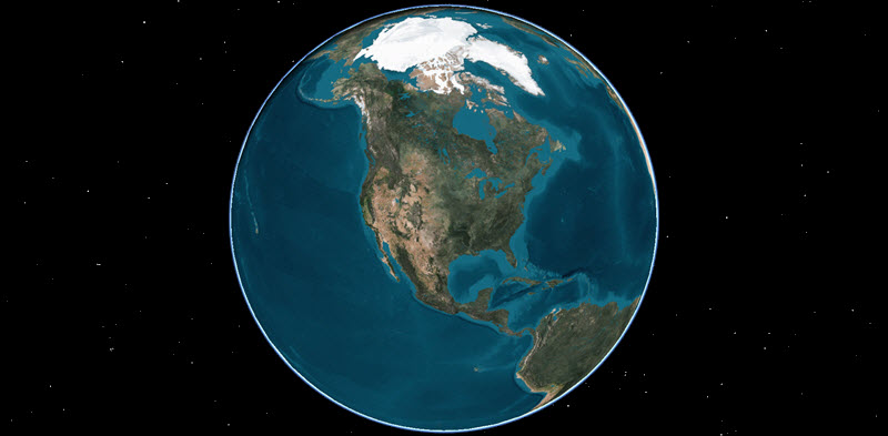
View of North America
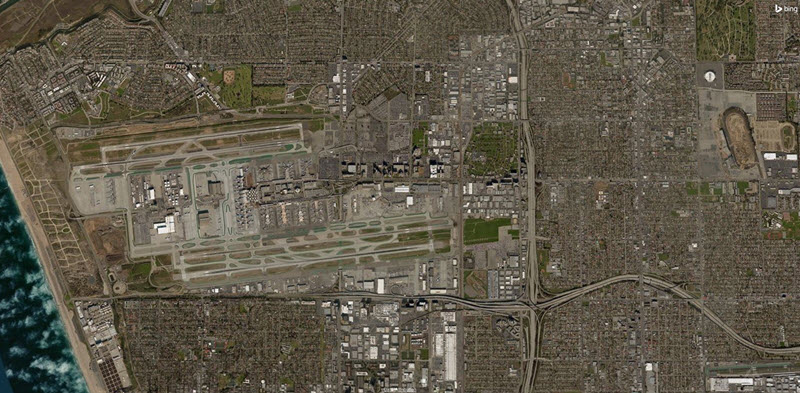
View of Los Angeles, California
Using Grab Globe
Although it is similar to the Grab Globe tool in the 2D Graphics window, there's one important difference: you need to turn Grab Globe on and use the Shift key along with the left mouse button.
Start with Zoom In prior to using Grab Globe.
- Click Grab Globe () in the 3D Window Defaults toolbar.
- Hold down the Shift key and the left mouse button and drag the mouse around the 3D Graphics window to grab the globe and pan.
- Release the Shift key and the left mouse button.
- Use the mouse scroll wheel to zoom in or out depending on the detail you are trying to obtain.
- Hold down the left mouse button and move the mouse around to rotate and tilt the globe. The globe pivots on the center point of the zoomed in area.
Using the mouse with the 3D Graphics window
You can use the mouse to interact with the 3D Graphics window. In addition to tools available in toolbars, the 3D Graphics window has additional mouse controls that manipulate the 3D Graphics window. Get familiar with the mouse controls.
- Double-click on any spot on the globe to display the latitude and longitude of the selected spot.
- Place your cursor on the 3D Graphics window globe.
- Hold down the left mouse button and move the mouse around to rotate the globe.
- In one motion, hold down the right mouse button and push the mouse away from you to Zoom out.
- While holding down the right mouse button, pull the mouse closer to you to Zoom in.
- Hold down the Shift key and left mouse button while moving the mouse around. This will pan and tilt the virtual camera.
- After you pan and tilt in the previous step, release the Shift key and left mouse button.
- Hold the left mouse button down and move the mouse around to keep the camera in a fixed point in space and change its orientation.
Using the Snap Frame tool
Just like in the 2D Graphics window, you can save pictures of the 3D Graphics window to a file or to the clipboard using the Snap Frame (![]() ) tool. Use Snap Properties (
) tool. Use Snap Properties (![]() ) to set the properties of the Snap Frame tool and to make high-resolution images of a 3D Graphics window.
) to set the properties of the Snap Frame tool and to make high-resolution images of a 3D Graphics window.
Using the 3D Graphics toolbar
The 3D Graphics toolbar provides easy access to the most frequently used options and tools used to control the graphical display of your scenario in the 3D visualization windows. You will focus on the Home View, Flashlight, and 3D Measure tools, but you can see descriptions of all the tools on the 3D Graphics Toolbars Help page.
Using the Home View
The Home View displays the default view. If you are lost in your view, this is one of your best friends. It will bring you back to your home view with one click.
- Use the scroll wheel to zoom in close to the surface of the central body (Earth).
- Click Home View () in the 3D Graphics toolbar to reorient the 3D Graphics camera back on the default Earth-centered view.
Using the Flashlight
The Flashlight illuminates the globe and objects when they aren't located in sunlight. This is visual only. Analytically, actual lighting conditions still apply. You define the Flashlight settings in the 3D Graphics window properties.
- Rotate the globe until you're viewing the dark side of the Earth.
- Click Flashlight (
 ) in the 3D Graphics toolbar.
 - When finished, click Flashlight () again to disable it.
Using the 3D Measure tool
Similar to the 2D Graphics window's Measure tool, the 3D Measure tool measures the shortest distance between two points and the azimuth bearing in the 3D Graphics window.
- Click 3D Measure (
 ) in the 3D Graphics toolbar.
 - Place your cursor on the 3D Graphics window map.
- Hold down the left mouse button and drag the cursor to another spot on the map.
- Release the left mouse button. The distance between the two points and the azimuth bearing display in the lower left hand corner of the Status Bar and the Message Viewer.
Remember, the data are only as good as where you clicked on the map. In general, this tool is a good way to get an approximate distance between two points. If you require exact distances, you will need to measure the distance between two STK objects using the Report & Graph Manager. You can learn more about reports and graphs in Lesson 3: Access Reports and Graphs tutorial.
Using the Globe Manager toolbar
Globe Manager (![]() ) is a very important visualization tool. You can use it to populate the central body of your 3D Graphics window with imagery, terrain, data sets, and tile sets. Globe Manager is covered in later tutorials; you can focus on Globe Manager by completing the Using Globe Manager in STK tutorial.
) is a very important visualization tool. You can use it to populate the central body of your 3D Graphics window with imagery, terrain, data sets, and tile sets. Globe Manager is covered in later tutorials; you can focus on Globe Manager by completing the Using Globe Manager in STK tutorial.
Using the Microsoft Bing™ Maps toolbar in the 3D Graphics window
The Microsoft Bing™ Maps (![]() ) toolbar allows you to choose a background image (Microsoft Bing™ Maps or Basic.bmp) in 3D Graphics windows. This tool works the same in the 3D Graphics window as it does in the 2D Graphics window.
) toolbar allows you to choose a background image (Microsoft Bing™ Maps or Basic.bmp) in 3D Graphics windows. This tool works the same in the 3D Graphics window as it does in the 2D Graphics window.
Understanding Terrain Server
The Terrain Server distributes Earth terrain data for visualization or analysis. By default, the STK application connects to the Ansys Geospatial Data Cloud, which is available via an internet connection to all users of the STK application.
- Check your internet connection via your status bar. If online operations are available (
 ), continue to the next step. If online operations are not available (
 ), troubleshoot online operations or skip to the next section.
 - Zoom In () on an area of interest in the 3D Graphics window.
- Use the mouse scroll wheel to zoom very close to the Earth's surface.
- Hold down the left mouse button and push the mouse away from you to tilt the globe on its side.
You should see terrain features. If you happen to be zoomed into a flat area, readjust your area to a more hilly or mountainous location. If you find yourself under the terrain, zoom out a bit and readjust your view.
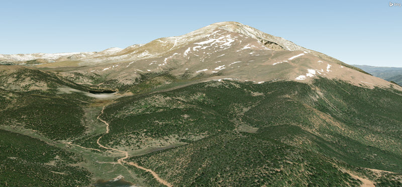
Terrain Server Streaming Terrain
Using the Animation toolbar
The Animation toolbar helps you control the progression of your scenario. With a few clicks, you can control the start time, stop time, and how quickly the scenario progresses from start to stop. Use the animation controls to play through the scenario.
- Select the Window menu.
- Select Tile Vertically.
- Click Home View () in the 3D Graphics toolbar.
- In the Animation toolbar, click Start (
 ) to have the scenario animate forward in time from the current point.
 - Click Pause (
 ) to stop the scenario animation.
 - Click Step Forward (
 ) or Step Backward (
 ) to progress one step at a time through the scenario.
 - Click Reverse (
 ) to have the scenario animation rewind from the current point.
 - Experiment with increasing (
 ) and decreasing (
 ) the speed of the animation, which by default is 10 seconds. This will also affect the time step of Step Forward and Step Backward as well.
 - At any point, click Reset (
 ) to have the scenario return to the start time. This does not reset the speed of the animation.
Besides the buttons that increase and decrease animation speed, you can set a scenario to run at a particular speed using the following yellow clock symbols:
- Normal Animation Mode (
 ): The scenario animates in accordance with the scenario time you defined when creating the scenario and the defined time steps. Again, by default, the defined time steps are 10 seconds.
 - Real-Time Animation Mode (
 ): The scenario animates in real time in accordance with your computer's internal clock.
 - X Real-Time Animation Mode (
 ): The scenario sets the playback to a sped-up or slowed-down version of real time. For instance, entering a value of 1 will have the scenario run at real time. Entering a value greater than 1 speeds up the animation. A value between 0 and 1 will slow down the animation.
Using the Timeline View
Use the Timeline View to visualize a variety of time intervals within your scenario. The user interface of the Timeline View is comprised of a toolbar, three timelines, and rows of time components.
Understanding the Time Display
The Time Display is the largest and most granular of the timelines. Use the gray pointer to adjust the animation time to any point within the Time Display's current boundary to visualize time events.
- Click Home View () in the 3D Graphics toolbar to reset the view.
- Click Zoom Out () in the 2D Window Defaults toolbar to zoom out of the 2D window. Click Zoom Out () as many times as needed until the 2D map fills the display window.
- While looking at the 2D Graphics or 3D Graphics window, put your cursor on the Gray Pointer (
 ) in the Timeline View.
 - Hold down the left mouse button and slide the Gray Pointer to the right.
- Notice the globe rotating and the day-night shading on the 2D Graphics window moving as you scroll through the scenario time period.
Saving your work
There are several different ways to save your scenario:
- You can save your scenario in the folder created when using the steps at the beginning of this tutorial.
- You can use the Save As procedure to create a new folder.
- You can create a visual data file, or VDF.
Saving the scenario in the current folder
You already have your scenario saved in a unique folder. You created this folder by saving your scenario as instructed at the beginning of this tutorial.
- Close any open windows except for the 2D and 3D Graphics windows.
- Click Save ().
Moving external files to your scenario folder
There are times that you might want to add external files to your scenario folder (for example, image, .txt, and .csv files). This is common when sending your scenario to AGI Support or Certification.
The common location if you use the default path during the STK application setup for STK_ODTK 13 is:
- C:\Users\<username>\Documents\STK_ODTK 13\<Scenario name>
All you have to do is copy and paste or click and drag the required files into the scenario folder.
Saving a scenario to a new folder
There are instances when you may want to save the current scenario in a new location, and possibly with a new scenario name. This step often causes people to save their scenario outside of a unique folder. If you end up saving multiple scenarios in the same folder, or worse, on your desktop, you will run into problems when analyzing data. Remember: you always want your scenario in a unique folder. It's a good idea to give it a try.
- Open the File menu.
- Select Save As... in the File menu.
- Select STK User (
 ) in navigation pane on the left side of the Save As dialog box.
 - Click New folder in the ribbon.
- Rename the folder anything you desire.
- Select the new folder you created.
- Click .
- When the folder opens, enter a name in the File name field.
- Check to make sure Scenario Files (*.sc) is selected for the Save as type.
- Click .
This is where a lot of people make a mistake using the Save As procedure. They forget to select the new folder and end up placing the scenario and all of its files out in the open in the STK_ODTK 13 folder. Do this more than once with different scenarios and you will run into problems.
This will be the name of the Scenario object of your new scenario, so it follows the naming rules of all objects in the STK application.
You now have a complete copy of your original scenario, but now it's located in a different folder and has a new scenario name.
If you have non-STK files, such as text or CSV files, in the original scenario folder, they won't transfer to the new folder. You must manually move them or copy them to your new scenario folder.
Creating a Visual Data File (VDF)
You can convert your STK scenarios to Visual Data (.vdf) files for sharing your scenario with managers, coworkers, customers and prospects for collaboration, without the need for a full STK installation. Although it's not a true compressed file, creating a VDF places all your scenario files into one file. There may also be instances when you need to send your scenario to AGI Support or Certification where you will be instructed to create a VDF and send them the file.
- Select the File menu at the top of STK.
- Select VDF Setup... in the File menu.
- Select the Exclude Install Files check box when the VDF Setup dialog box opens.
- Look at the Custom/User Data panel.
- Look at the Quick Reports For STK Viewer list.
- Click .
- Ensure the Save location is in your scenario folder.
- Click .
Selecting the Exclude Install Files check box reduces the VDF size by excluding files that are part of the STK application's installation from the VDF.
You can select the Copy scenario folder contents check box to include both scenario files and non-STK files, like Word document and Excel workbooks, with the VDF file.
Quick Reports will be covered in the Access Reports and Graphs tutorial. If you have Quick Reports, you can include them in your VDF.
Closing the scenario
This seems simple enough, but you have a couple of choices to make. Do you want to continue working with a different scenario, or do you want to completely shut down the STK application?
Closing the scenario but not the STK application
If you're moving on to a new or different scenario, you'll want to keep the STK application open.
- Select the File menu.
- Select Close in the File menu.
- Click
 Open a Scenario in the Welcome to STK dialog box.
 - Select one of your scenario folders in the Open window.
- Click .
- Select the STK scenario file.
- Click .
You can now create a new scenario or open an existing scenario. The STK application remains open.
If you don't see the Welcome to STK dialog box — for example, because you selected the Do not show me this again check box when you last had it open — you can re-enable it in the STK application's general settings by selecting Preferences... in the Edit menu, selecting the General page, and selecting the Use the "Welcome to STK" wizard check box in the Behavior panel.
Closing the scenario and the STK application
Use these steps if you're saving your scenario and closing the STK application.
- Close any open windows except for the 2D and 3D Graphics windows.
- Save () your work.
- Close the STK Application.
Summary
You got a thorough introduction of the STK: New Scenario Wizard and a brief outline of STK tools and windows such as the Object Browser and the Timeline View. The bulk of the information in this tutorial helped you to become familiar with the functions and tools of the 2D and 3D Graphics windows. These windows are important for your situational awareness while using the STK application. You ended by understanding how to save and close a scenario.
Continue to Lesson Two: Objects and Properties.
On your own
Throughout the tutorial, hyperlinks to STK Help files were provided that pointed to in-depth information of various tools and functions. Now is a good time to go back through this tutorial and view that information. Try rearranging windows and tools. Enable other tools and view their functions.