Part 17:
STK Premium (Space) or STK Enterprise
You can obtain the necessary licenses for this tutorial by contacting AGI Support at support@agi.com or 1-800-924-7244.
This lesson requires version 12.7 of the STK software or newer to complete in its entirety.
The results of the tutorial may vary depending on the user settings and data enabled (online operations, terrain server, dynamic Earth data, etc.). It is acceptable to have different results.
Capabilities covered
This lesson covers the following capabilities of the Ansys Systems Tool Kit® (STK®) digital mission engineering software:
- STK Pro
- Astrogator
Problem statement
Engineers and operators require a quick way to design high-fidelity spacecraft trajectories for mission planning and operations. In this scenario, you will design a launch from a launch pad and successfully inject a satellite into a geosynchronous equatorial orbit (GEO).
Solution
Use the STK/Astrogator® capability to design:
- A basic launch phase to place a satellite into a parking orbit (low Earth orbit, or LEO)
- A transfer orbit injection (TOI) maneuver to transfer from LEO to GEO
- A synchronized orbit injection (SOI) maneuver to circularize the orbit at GEO
What you will learn
Upon completion of this tutorial, you will have a basic understanding of:
- The Astrogator capability
- The Launch Vehicle object
Creating a new scenario
First, you must create a new scenario, then build from there.
- Launch the STK application (
 ).
). - Click
 Create a Scenario in the Welcome to STK dialog box.
 - Enter the following in the New Scenario Wizard:
- Click when you finish.
- Click Save (
 ) after the scenario loads. The STK software creates a folder with the same name as your scenario for you.
 - Verify the scenario name and location in the Save As dialog box.
- Click .
| Option | Value |
|---|---|
| Name | STK_Astrogator |
| Location | Default |
| Start | Default |
| Stop | + 5 days |
Save (![]() ) often during this lesson!
) often during this lesson!
Updating the Insert STK Objects tool
Ensure the Launch Vehicle object appears in the Insert STK Objects tool.
- Click in the Insert STK Objects tool.
- Select the Show check box for Launch Vehicle when the Preferences dialog box opens.
- Click to confirm your change and to close the Preferences dialog box.
Creating a launch vehicle
Insert a Launch Vehicle object. A Launch Vehicle object models the properties and behavior of a vehicle that follows an ascent trajectory from a launch point to an orbit insertion point.
- Select Launch Vehicle (
 ) in the Select an Object to Be Inserted list in Insert STK Objects tool.
 - Select the Insert Default () method in the Select a Method list.
- Click .
- Right-click on LaunchVehicle1 () in the Object Browser.
- Select Rename in the shortcut menu.
- Rename LaunchVehicle1 () LaunchToLEO.
Selecting the simple ascent propagator
Propagators define the path that the launch vehicle will follow. Use the simple ascent propagator to define the ascent trajectory from a launch point to an orbit insertion point. The simple ascent propagator creates an ascent trajectory based on launch and insertion parameters. The trajectory is a simple curve rising vertically from the launch pad that turns over smoothly to insert the launch vehicle into orbit with a zero flight path angle at the insertion point using the specified velocity.
- Right-click on LaunchToLEO ().
- Select Properties (
 ) in the shortcut menu.
 - Select the Basic - Trajectory page when the Properties Browser opens.
- Ensure the Propagator is set to SimpleAscent.
- Enter 7.3 km/sec in the Burnout Velocity field.
- Click to confirm your change and to keep the Properties Browser open.
- Select the 2D Graphics - Attributes page.
- Change the Color to teal.
- Click to confirm your changes and to close the Properties Browser.
This is the velocity of the launch vehicle at the designated Stop Time (burnout). A velocity of 7.3 kilometers per second will keep the resulting orbit nearly circular.
Viewing the launch vehicle trajectory
View LaunchToLEO's launch vehicle trajectory and ground track in the 3D Graphics window.
- Bring the 3D Graphics window to the front.
- Zoom To LaunchToLEO ().
- Use your mouse to zoom out so you can see the launch vehicle trajectory and ground track.
- Notice that the Launch Vehicle's () default location is a launch pad at Cape Canaveral, Florida.
- Notice it's trajectory ends at burnout.
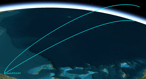
Launch Vehicle Trajectory
Inserting a satellite
Insert a Satellite object, which you will use to create the orbit.
- Insert a Satellite (
 ) object using the Insert Default () method.
 - Rename Satellite1 () GEO_Sat.
Using the Astrogator capability
You will use Astrogator to design your spacecraft trajectory. The Astrogator capability contains specialized analysis for interactive orbit maneuver and spacecraft trajectory design. The Astrogator capability acts as one of the several types of
- Open GEO_Sat's () Properties ().
- Select the Basic - Orbit page when the Properties Browser opens.
- Open the Propagator drop-down list.
- Select Astrogator.
Setting up the Mission Control Sequence
The Mission Control Sequence is the core of your space mission scenario. The MCS functions as a graphical programming language, in which mission segments dictate how Astrogator calculates the trajectory of the spacecraft based on the general settings that you specify for the MCS itself. You can
The left side of the MCS is represented schematically by a tree structure, which lists the segments that make up the MCS and depicts their relationships to each other. Above the tree is the MCS toolbar, which contains buttons that perform various MCS and individual segment operations. By default, an Astrogator satellite's MCS contains two segments: an Initial State segment and a Propagate segment that produce a low Earth orbit. The right side of the window contains the parameters of the segment that is currently selected in the MCS Tree.
Deleting the Initial State segment
Since you are modeling your mission beginning with a Launch Vehicle, remove the Initial State segment.
- Select Initial State (
 ) in the MCS.
 - Click Delete Segment (
 ) on the MCS toolbar.
 - Click to confirm the deletion.
Adding a Follow segment
A Follow segment is used to set a spacecraft to follow another vehicle (such as a Satellite or Launch Vehicle) at a specified offset, and to separate from that vehicle upon meeting specified conditions. Insert a new Follow segment to set GEO_Sat to follow LaunchToLEO, and then separate from LaunchToLEO at the end of its ephemeris.
- Right-click on Propagate (
 ) in the MCS.
 - Select Insert Before... in the shortcut menu.
- Select Follow (
 ) when the Segment Selection dialog box opens.
 - Click to confirm your selection and to close the Segment Selection dialog box.
Defining the Follow segment
To define a Follow segment, you must set the general parameters to describe the epoch and nature of the following operation, then specify the joining conditions, separation conditions, and spacecraft physical values as required by the general parameters you choose
- Select Follow () in the MCS.
- Select the General tab.
- Click the Leader ellipsis (
 ).
). - Select LaunchToLEO (
 ) when the Select Component dialog box opens.
 - Click to confirm your selection and to close the Select Component dialog box.
- Open the Joining drop-down list in the Additional Options panel.
- Select Join at End of Leader's Ephemeris.
The separation parameter is automatically set to Separate at End of Leader's Ephemeris. By selecting this joining parameter, GEO_Sat uses the LaunchToLEO's final ephemeris point as the initial and final state of the Follow Segment. The segment goes though the ephemeris points of LaunchToLEO, adding the specified offset to them and then adding these points to the ephemeris of GEO_Sat. Ephemeris points are not added until the joining condition is met and are added until the separation condition is met.
Setting the Fuel Tank configuration
In an Initial State, Follow, or Launch segment, you can
- Select the Fuel Tank tab.
- Set the following in the order shown:
- Click to confirm your changes and to keep the Properties Browser open.
| Option | Value |
|---|---|
| Tank Volume | 1.5 m^3 |
| Maximum Fuel Mass | 6000 kg |
| Fuel Mass | 5000 kg |
Running the Mission Control Sequence
To calculate the trajectory of the spacecraft you must run the Mission Control Sequence. Astrogator will proceed through the MCS and run each segment, generating an ephemeris for the spacecraft. As it runs the MCS, Astrogator carries the trajectory and state of the spacecraft determined so far from one segment to the next to calculate the trajectory of the spacecraft.
- Select Propagate () in the MCS.
- Note the current stopping condition is Duration, with a Trip value of 43200 sec (equivalent to half a day).
- Click Run Entire Mission Control Sequence (
 ) on the MCS toolbar.
 - Bring the 3D Graphics window to the front.
- Click Home View (
 ) to view GEO_Sat's () trajectory.
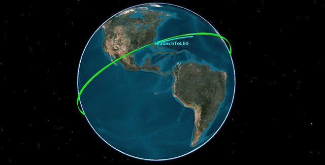
Satellite in Low Earth Orbit
Specifying the satellite's engine model
An
Creating a new engine model component
You'll duplicate a pre-built engine model in the
- Return to GEO_Sat's () Properties ().
- Click Component Browser (
 ) on the MCS toolbar.
 - Open the Show Component Type drop-down list when the Component Browser window opens.
- Select Astrogator Components.
- Select the Engine Models (
 ) folder in the View All Astrogator Components list.
 - Select Constant Thrust and Isp (
 ) in the Engine Models list on the right.
 - Click Duplicate component (
 ) on the Engine Models toolbar.
 - Enter Test Engine in the Name field when the Field Editor dialog box opens.
- Click to confirm your changes and to close the Field Editor dialog box.
Constant Thrust and Isp (![]() ) is read only and cannot be modified, so you must duplicate it before you can modify it.
) is read only and cannot be modified, so you must duplicate it before you can modify it.
Customizing your engine model
Modify the Constant Thrust and Isp engine model to specify the thrust and Isp for your engine.
- Double-click on the Test Engine () entry in the Engine Models list.
- Double-click on the Thrust entry when the Test Engine dialog box opens.
- Enter 13500 N in the Real Number field when the Real Number Field dialog box opens.
- Click to confirm your change and to close the Real Number Field dialog box.
- Double-click on the Isp entry.
- Enter 2000 s in the Real Number field when the Real Number Field dialog box opens.
- Click to confirm your change and to close the Real Number Field dialog box.
This high value will only affect the amount of fuel that the satellite will burn through over the course of the maneuvers. You are doing this so that you do not need to modify the spacecraft mass values several times over the course of the mission.
Adding the engine model component to your user collection
You can save a custom-built component to your
- Click .
- Click to confirm your changes and to close the Component Browser.
Note that Test Engine's icon has changed from ![]() to
to ![]() to indicate the component has been added to your user collection.
to indicate the component has been added to your user collection.
For more information about engine models, refer to the Astrogator
Designing the transfer orbit injection (TOI)
Use the Propagate segment to fly to the first maneuver time. The orbit is circular and therefore the burn can take place at any time and result in a similar Delta-V. You require an inclination as close as possible to zero once you enter GEO. To minimize the required Delta-V to both circularize and change inclination at GEO, you will combine those maneuvers into one. For that to be successful, the apogee of the transfer orbit will be the ascending or descending node of the orbit. This can be achieved by starting the TOI burn on either the ascending or descending node.
Updating the Propagate segment's properties
Rename the Propagate segment Prop to TOI to make its purpose in the MCS more clear.
- Return to GEO_Sat's () Properties ().
- Right-click on Propagate () in the MCS.
- Select Rename in the shortcut menu.
- Rename Propagate () Prop to TOI.
Updating the Stopping Condition
- Click New... (
 ) in the Stopping Conditions panel toolbar.
 - Select AscendingNode () when the New Stopping Condition dialog box opens.
- Click to confirm your selection and to close the New Stopping Condition dialog box.
- Select Duration in the Stopping Conditions panel.
- Click Delete () on the Stopping Conditions toolbar.
- Enter 2 in the Repeat Count field.
- Click to confirm your changes and to keep the Properties Browser open.
- Click Run Entire Mission Control Sequence () on the MCS toolbar.
This will end the Propagate segment on the second ascending node.
Defining a Target Sequence
You will use a Target Sequence to calculate the Delta-V required to move GEO_Sat into a transfer orbit. A Target Sequence acts as a structural element to define a maneuver and propagation in terms of the goals they are intended to achieve.
Inserting a new Target Sequence
Insert a new Target Sequence after the Propagate segment.
- Return to GEO_Sat's () Properties ().
- Right-click on Prop To TOI () in the MCS.
- Select Insert After... in the shortcut menu.
- Select Target Sequence (
 ) when the Segment Selection dialog box opens.
 - Click to confirm your selection and to close the Segment Selection dialog box.
- Rename Target Sequence () Start Transfer.
Inserting a Maneuver segment
You can nest any MCS segment within a Target Sequence, including another Target Sequence. The segments within a Target Sequence are defined in the same manner as they are in the MCS itself. Add a
- Right-click on Start Transfer () in the MCS.
- Select Insert After... in the shortcut menu.
- Select Maneuver (
 ) when the Segment Selection dialog box opens.
 - Click to confirm your selection and to close the Segment Selection dialog box.
- Click and drag the Maneuver () Segment below and nested inside Start Transfer ().
- Note that the default Maneuver type is Impulsive.
The Maneuver (![]() ) Segment appears below the Return (
) Segment appears below the Return (![]() ) Segment.
) Segment.
For
Updating the Maneuver segment's properties
An Impulsive Maneuver (![]() ) segment isn't visible in the 2D and 3D Graphics windows. Propagate segment colors are visible. Change the Maneuver segment's color to white to focus on the Propagate segments.
) segment isn't visible in the 2D and 3D Graphics windows. Propagate segment colors are visible. Change the Maneuver segment's color to white to focus on the Propagate segments.
- Right-click on Maneuver () in the MCS.
- Select Properties ... in the shortcut menu.
- Enter TOI in the Name field when the Edit Segment dialog box opens.
- Open the Color drop-down list.
- Select white.
- Click to confirm your changes and to close the Edit Segment dialog box.
Inserting a new Propagate Segment
Insert a
- Right-click on TOI () in the MCS.
- Select Insert After... in the shortcut menu.
- Select Propagate () when the Segment Select dialog box opens.
- Click to confirm your selection and to close the Segment Select dialog box.
Updating the Propagate segment's properties
Update the name and color of the Propagate segment.
- Right-click on Propagate () in the MCS.
- Select Properties ... in the shortcut menu.
- Enter Transfer in the Name field when the Edit Segment dialog box opens.
- Open the Color drop-down list.
- Select yellow.
- Click to confirm your changes and to close the Edit Segment dialog box.
- Click to confirm your changes and to keep the Properties Browser open.
Selecting the engine model
The Engine tab on a Maneuver segment defines the magnitude and the nature of the propulsion. The engine parameters specified on this tab are used primarily to define the maneuver direction when using a thruster set to seed a finite maneuver and to update the fuel mass. You can use Engine Model to quickly model the firing of a single engine. Use the Test Engine model you updated earlier.
- Select TOI () in the MCS.
- Select the Engine tab.
- Click the Engine Model ellipsis () in the Propulsion Type panel.
- Select Test Engine (
 ) when the Select Component dialog box opens.
 - Click to confirm your selection and to close the Select Component dialog box.
Selecting the control parameter
The actions that the Target Sequence takes are determined by the profiles that are defined for it. A Search profile defines goals and changes variables to achieve them. A differential corrector search profile uses a differential correction algorithm to achieve a goal value or set of values. The values that the profile targets are called independent variables. The values that define the goal of the profile are called dependent variables. When the Target Sequence runs, it will change the values of the independent variables to achieve the goal. You can use any element of a nested MCS segment or linked component as an
- Select the Attitude tab.
- Note that the default Attitude Control is Along Velocity Vector.
- Select the Delta-V Magnitude target (
 ).
). - Click to confirm your changes and to keep the Properties Browser open.
Attitude Control specifies the mode in which the maneuver pointing direction is prescribed. With the Along Velocity Vector selection, the satellite object’s attitude is such that the Delta-V vector aligns with the spacecraft's inertial velocity vector.
Notice the target now has a check mark (![]() ). Selecting the target makes Delta-V Magnitude an independent variable. This tells Astrogator to determine the Delta-V magnitude based on user determined results. You will set up those results in an upcoming section.
). Selecting the target makes Delta-V Magnitude an independent variable. This tells Astrogator to determine the Delta-V magnitude based on user determined results. You will set up those results in an upcoming section.
For more information about differential correctors, refer to the Astrogator
Propagating to apoapsis
Update the Transfer Propagate segment's Stopping Condition to stop at apoapsis.
- Select Transfer () in the MCS.
- Click New... () in the Stopping Conditions panel toolbar.
- Select Apoapsis () when the New Stopping Condition dialog box opens.
- Click to confirm your selection and to close the New Stopping Condition dialog box.
- Select Duration in the Stopping Conditions panel.
- Click Delete () on the Stopping Conditions toolbar.
- Click to confirm your changes and to keep the Properties Browser open.
Selecting the results variable
Dependent variables for a differential corrector profile are defined in terms of calculation objects. Use a calculation object for the radius of the orbit, R Mag, to be used as the dependent variable.
- Select Transfer () in the MCS.
- Click beneath the MCS Tree.
- Expand (
 ) the Spherical Elems () folder in the Available Components list when the User - Selected Results - Transfer dialog box opens.
 - Select R Mag ().
- Click Insert Component (
 ) to move R Mag () to the selected components list.
 - Click to confirm your selection and to close the User - Selected Results - Transfer dialog box.
This will enable you to set the radius of orbit at the end of the Propagate Segment.
Setting up the differential corrector profile
You can configure a Target Sequence to execute in many different ways depending on the solution you are trying to achieve. Set up the differential corrector profile to change the Delta-V Magnitude to achieve a desired radius of orbit.
- Select Start Transfer () in the MCS.
- Open the Action drop-down list.
- Select Run active profiles.
Selecting run active profiles runs the Mission Control Sequence allowing the active profiles to operate.
Setting the control parameter
Use the Delta-V Magnitude as the control parameter (independent variable) in the Target Sequence.
- Select Differential Corrector in the Profiles panel.
- Click Properties... () on the Profiles toolbar.
- Ensure the Variables tab is selected when the Differential Corrector dialog box opens.
- Select the Use check box for ImpulsiveMnvr.Pointing.Spherical.Magnitude in the Control Parameters panel.
Each independent variable that you selected is listed in the Control Parameters section of the Variables tab.
Setting the equality constraints (Results)
Set R Mag as the equality constraint (dependent variable) with a goal of 42,238 km. Astrogator will use R Mag to determine the required Delta-V magnitude.
- Select the Use check box for R_Mag in the Equality Constraints (Results) panel.
- Click on the Desired Value cell.
- Enter 42238 km in the Desired Value cell.
- Click to confirm your changes and to close the Differential Corrector dialog box.
- Click to confirm your changes and to keep the Properties Browser open.
- Save () your scenario.
Each dependent variable that you selected is listed in the Equality Constraints (Results) section of the Variables tab.
The value that you want to achieve.
Running the Entire Mission Control Sequence
With your Target Sequence configured, run the entire Mission Control Sequence.
- Click Run Entire Mission Control Sequence () on the MCS toolbar.
- When complete, look at the top of the STK application.
- Look at the StartTransfer.Differential Corrector target status window.
- Close the StartTransfer.Differential Corrector target status window.
- Bring the 3D Graphics window to the front.
During the execution of one or more Target Sequences, Target Status windows appear and provide valuable information on their progress, including a message informing you whether or not running the entire MCS converged or didn't converge. You can close these windows individually, or you can clear them all at once by left-clicking the target icon (![]() ) in the upper-left corner of one of the windows and selecting "Close All Targeting Status Windows."
) in the upper-left corner of one of the windows and selecting "Close All Targeting Status Windows."
This shows you data based on running the active profile.
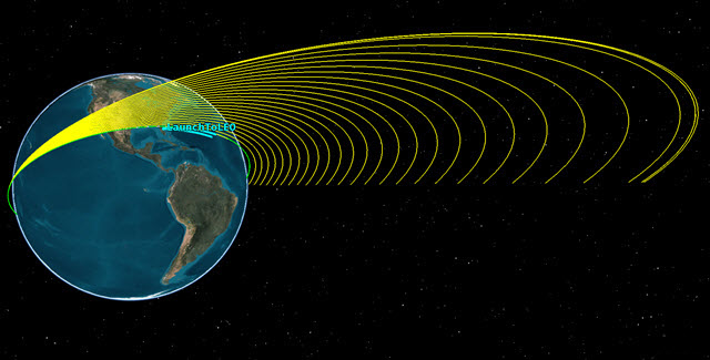
TOI Iterations
You can see the iterations, the last one placing the satellite at the desired location and altitude.
Designing the synchronized orbit injection (SOI)
Now that the transfer has been analyzed, you will follow a similar process to create the SOI maneuver and circularize the orbit at GEO. At the same time, you will bring the inclination to 2 deg. You will target the inclination slightly above the desired inclination, so that it will drift down to the desired inclination (0 to 1 degree) over time.
Inserting another Target Sequence
Create another Target Sequence to create the SOI and circularize the orbit at GEO.
- Return to GEO_Sat's () Properties ().
- Right-click on the bottom Return (
 ) Segment in the MCS.
 - Select Insert Before... in the shortcut menu.
- Select Target Sequence () when the Segment Selection dialog box opens.
- Click to confirm your selection and to close the Segment Selection dialog box.
- Rename Target Sequence () Finish Transfer.
Inserting a Maneuver segment
Insert a Maneuver (![]() ) segment. You will solve for the X (Velocity) & Y (Normal) components and the Delta-V vector in those references axes needed to achieve a circular orbit at GEO.
) segment. You will solve for the X (Velocity) & Y (Normal) components and the Delta-V vector in those references axes needed to achieve a circular orbit at GEO.
- Right-click on Finish Transfer () in the MCS.
- Select Insert After... in the shortcut menu.
- Select Maneuver () when the Segment Selection dialog box opens.
- Click to confirm your selection and to close the Segment Selection dialog box.
- Click and drag the Maneuver () Segment below and nested in Finish Transfer ().
The Maneuver (![]() ) Segment appears below the return (
) Segment appears below the return (![]() ) Segment.
) Segment.
Updating the Maneuver segment's properties
As before, change the Maneuver segment's name and its color to white.
- Right-click on Maneuver () in the MCS.
- Select Properties ... in the shortcut menu.
- Enter SOI in the Name field when the Edit Segment dialog box opens.
- Open the Color drop-down list.
- Select white.
- Click to confirm your changes and to close the Edit Segment dialog box.
Inserting a Propagate segment
Insert a Propagate Segment, which will be used to determine the stopping condition.
- Right-click on SOI () in the MCS.
- Select Insert After... in the shortcut menu.
- Select Propagate () when the Segment Select dialog box opens.
- Click to confirm your selection and to close the Segment Select dialog box.
Updating the Propagate segment's properties
Edit the Propagate segment's name and color.
- Right-click on Propagate () in the MCS.
- Select Properties ... in the shortcut menu.
- Enter Prop 1 Rev in the Name field when the Edit Segment dialog box opens.
- Open the Color drop-down list.
- Select blue.
- Click to confirm your changes and to close the Edit Segment dialog box.
- Click to confirm your changes and to keep the Properties Browser open.
Setting the engine model
Use the Test Engine model you created earlier.
- Select SOI () in the MCS
- Select the Engine tab.
- Click the Engine Model ellipsis () in the Propulsion Type panel.
- Select Test Engine () when the Select Component dialog box opens.
- Click to confirm your selection and to close the Select Component dialog box.
Selecting the control parameter
Use Thrust Vector as the attitude control setting. Then select the Delta-V vector's Cartesian X (Velocity) and Y (Normal) as the independent variables.
- Select the Attitude tab.
- Open Attitude Control drop-down list.
- Select Thrust Vector.
- Select the X (Velocity) target ().
- Select the Y (Normal) target ().
- Click to confirm your changes and to keep the Properties Browser open.
The thrust vector describes the direction of acceleration applied to a satellite. This direction is opposite to the exhaust of an engine. For example, for a single chemical rocket engine mounted to a satellite, the thrust vector is opposite to the direction of the center of the exhaust plume flames. If the satellite uses more than one engine together in a thruster set, the thrust vector is along the direction of the combined effective acceleration. This direction is determined by calculating the sum of the acceleration vectors of each individual thruster. With this attitude control setting, you specify the Delta-V vector in some reference frame using either Cartesian or spherical components. Astrogator then computes the attitude so that the total thrust vector in the body frame, as specified by the thruster set or engine model, aligns with this vector in the reference axes.
Propagating for one day
Update the Prop 1 Rev Propagate segment's Duration Stopping Condition to stop after one day.
- Select Prop 1 Rev () in the MCS.
- Enter 1 day in the Trip field in the Stopping Conditions panel.
- Click to confirm your change and to keep the Properties Browser open.
Selecting the results variable
Set Eccentricity and Inclination to be used as the equality constraints.
- Ensure Prop 1 Rev () is selected in the MCS.
- Click at the bottom of the MCS.
- Expand () the Keplerian Elems () folder in the Available Components list when the User - Selected Results - Prop 1 Rev dialog box opens.
- Insert () the Eccentricity () component on the selected components list.
- Insert () the Inclination () component on the selected components list.
- Click to confirm your selections and close the User - Selected Results - Prop 1 Rev dialog box.
- Click to confirm your changes and to keep the Properties Browser open.
Setting up the differential corrector profile
Set up the differential corrector profile to change the Delta-V Magnitude to achieve a desired radius of orbit.
- Select Finish Transfer () in the MCS.
- Open the Action drop-down list.
- Select Run active profiles.
Setting the control parameters
Use the Delta-V vector's Cartesian X (Velocity) and Y (Normal) as the Control Parameters (independent variables).
- Select Differential Corrector in the Profiles panel.
- Click Properties... () on the Profiles toolbar.
- Select the Use check box for ImpulsiveMnvr.Pointing.Cartesian.X in the Control Parameters panel when the Differential Corrector dialog box opens.
- Select the Use check box for ImpulsiveMnvr.Pointing.Cartesian.Y.
Setting the equality constraints (Results)
Set Eccentricity and Inclination as the Equality Constraints (dependent variables). Target an eccentricity of 0 within a 0.001 tolerance, and a 2 degree inclination within 0.01 degree of tolerance.
- Select the Use check box for Eccentricity in the Equality Constraints (Results) panel.
- Enter 0.001 in the Tolerance field.
- Select the Use check box for Inclination.
- Select the Desired Value cell.
- Enter 2 deg in the Desired Value cell.
- Enter 0.01 deg in the Tolerance field.
- Open the Method drop-down list in the Scaling panel.
- Select By tolerance.
- Click to confirm your changes and to close the Differential Corrector dialog box.
- Click to confirm your changes and to keep the Properties Browser open.
The profile will stop when it achieves a value within this range of the Desired Value.
The scaling method improves numerical behavior if the enabled parameters have diverse magnitudes.
Running the entire Mission Control Sequence
With your SOI Target Sequence configured, run the entire MCS.
- Click Run Entire Mission Control Sequence () on the MCS toolbar.
- Look at the Finish Transfer.Differential Corrector: Finished data window.
- Close both the Start Transfer.Differential Corrector and Transfer.Differential Corrector Targeting Status windows.
- Bring the 3D Graphics window to the front.
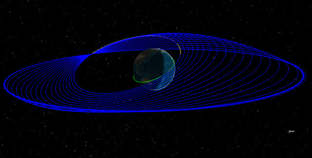
SOI Iterations
You can see the iterations, the last one placing the satellite at the desired eccentricity and inclination.
Removing the iterations
Remove the visible iterations in the 3D Graphics window by adding a final Propagate segment.
- Return to GEO_Sat's () Properties ().
- Right-click on the Bottom Return (
 ) Segment.
 - Select Insert Before... in the shortcut menu.
- Select Propagate () when the Segment Selection dialog box opens.
- Click to confirm your selection and to close the Segment Selection dialog box.
- Click Run Entire Mission Control Sequence () on the MCS toolbar.
- Close both the Start Transfer.Differential Corrector and Transfer.Differential Corrector Targeting Status windows.
- Bring the 3D Graphics window to the front.
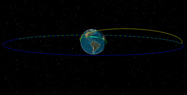
Final Orbit
Generating an MCS Segment Summary report
In addition to the reports that can be created using the Report & Graph Manager available for any STK object, Astrogator can generate three
- Return to GEO_Sat's () Properties ().
- Select Start Transfer () in the MCS.
- Click Summary (
 ) on the MCS toolbar.
 - Look at the data in the report when the report opens.
- When finished, close (
 ) the summary report.
 - Select Finish Transfer ().
- Click Summary () on the MCS toolbar.
- Look at the data in the report when the report opens.
Saving your work
Clean up and close out your scenario.
- Close any open reports, tools, and properties.
- Save () your work.
Summary
This was a basic introduction to Astrogator. In this lesson, you did the following:
- Used a Launch Vehicle object to launch a vehicle that followed an ascent trajectory from a launch point to an orbit insertion point
- Inserted a Satellite object, switched the propagator to Astrogator and used a Follow Segment. This allowed the Satellite to follow the Launch Vehicle object, to separate from the Launch Vehicle at the end of its trajectory, and to place the Satellite object into a LEO.
- Used a Target sequence, a Maneuver segment, and a Propagate segment to place the Satellite orbit into a TOI
- Finalized its orbit by creating another Target Sequence that placed the Satellite into a GEO
- Used an MCS Segment Summary report to determine maneuver times, required Delta-V, estimated burn duration, and estimated fuel usage
On your own
Throughout the tutorial, hyperlinks were provided that pointed to in-depth information of various tools and functions. Now is a good time to go back through this tutorial and view that information. Further Astrogator tutorials can be found HERE.